[Lab02] Some notes on Inverter, Theory, and Reality 이론과 실제의 간극, 그리고 인버터의 이모저모

The experiments I’m introducing were conducted about three years ago, so the vividness of those moments might have faded a little. However, the most valuable discovery from that time was not just the fact that I completed the circuits, but that I got a true taste of the gap between theory and reality.

Typically, when creating variations in a circuit, the first element people look to is the resistor. I’ve previously shown examples using a xylophone as a resistive body. However, the most interesting harvest from this experiment (perhaps felt more strongly due to my lack of prior knowledge) was the change that occurred when swapping various capacitors.
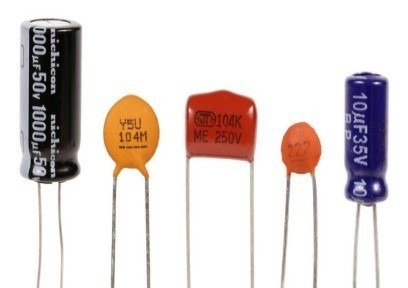
Various Capacitors

In reality, there are so many different types of capacitors. Depending on their material and construction (polarized or not, degree of stability, etc.), and how they are connected, the dynamics of the circuit change significantly. The calculated values in an RC circuit are actually quite abstract figures; in a real-world environment, staying exactly at those numbers requires immense effort to prevent noise. For me, however, that discrepancy is exciting. As long as basic operation is guaranteed, all these unpredictabilities become meaningful.

While a change in resistance directly alters the frequency by slowing the flow of current, the capacitor not only sympathizes with that process but also becomes a key element in determining the timbre. Even with the same capacity, using a capacitor made of a different material changes the texture because the capacitor itself acts as a kind of filter. For those of us who handle circuits as musical material, this is an indispensable element.

Another thing that awakened my naivety was the role of feedback. My previous experience with feedback was primarily positive feedback in audio signals—a phenomenon where a specific frequency explodes and reinforces itself. Because I had focused mostly on unwanted howling or chaotic instability, adapting to the completely different nature of feedback found within a circuit was quite challenging. I wondered, “How can feedback create stability?” Believing that feedback always symbolized instability was a very one-dimensional thought.

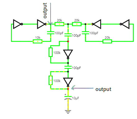
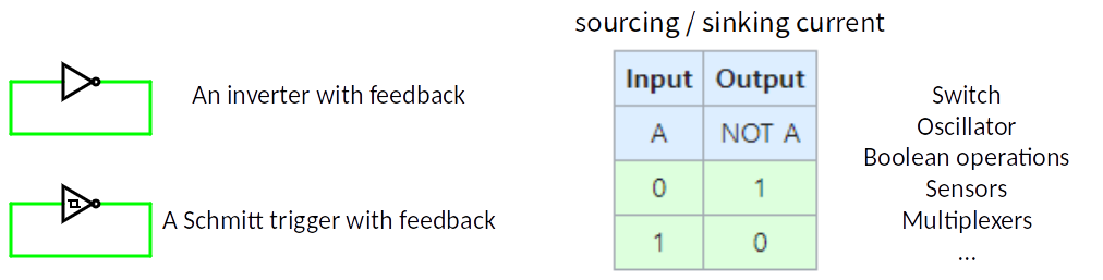
Feedback in a circuit mainly takes the form of negative feedback, where the output suppresses the input. The structure of an inverter oscillator utilizes this very principle. By returning the output to the input to constantly flip the state, with the speed controlled by R and C, a steady oscillation is created. In other words, feedback here serves as a stabilizer that sustains the oscillation while keeping the system within a specific orbit. The diagram below shows an abstract form of feedback without R and C.

In the previous 4049 inverter experiment, I used ceramic capacitors to allow the voltage to swing between two points. When used to ‘copy’ and return a signal from a specific point, these are sometimes called ‘feedback capacitors.’ Since the 4049 lacks hysteresis, the transition between 0 and 1 is extremely sensitive and unstable. The numerous noises generated during this process mix into the output, which, from a tinkering perspective, becomes very interesting musical material. On the other hand, a Schmitt Trigger filters out such ambiguous noise sharply, making it more suitable for clean oscillator design rather than experimental purposes.

Furthermore, the 4049 has a random distribution of Vss and Vdd for each input, making the starting point difficult to predict. Without an initial connection, the voltage maintains a random value; the moment a connection is made, it starts operating from an already random voltage level. It’s a truly thrilling point.

A few more notes on inverters:

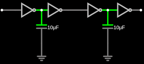
A series of inverters can create a delay, influenced by two main factors:

  1. Capacitor values: Capacitor Delay
  2. Gate latencies: Connecting an odd number of inverters in series is called a “ring oscillator.” A minute amount of time, measured in nanoseconds, is required for the signal to pass through each gate, depending on the IC chip’s design. Gate Latency

Note that an odd number of inverters must be connected for oscillation to occur. If an even number is connected, the output becomes latched to the same state as the input, and the circuit stays in one state without oscillating. Even Number Latch
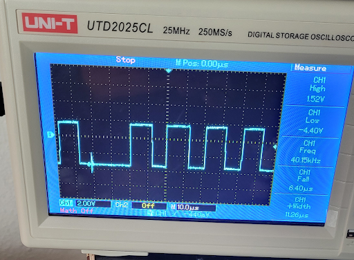
To create a distinct time delay audible to the ear in an analog circuit, a separate “clock” device is required. The gate latency method described above is closer to a phase shifter that subtly pushes the phase of the waveform, rather than a traditional delay, as it operates on a fleeting nanosecond scale.
[Lab 01] Crackle Inverter

I previously shared the background behind why I began these circuit experiments. However, starting something for the first time is always a challenge, as the initial point of departure sets the direction for everything that follows.

My choice emerged naturally from experience. When I first started these experiments, I was at a level where I could build very basic oscillators. Consequently, it felt intuitive to begin with the Integrated Circuits (ICs) I already had on hand. At the time, I had a sort of circuit practice toolbox that my friend Satoshi had passed down to me, which contained various IC chips. My starting point was to organize them, figure out what each one did, and pick one to work with. The most abundant chip in the box was the 4049 CMOS. I discovered it was a NOT gate; seeing that it simply outputted 1s and 0s, I thought it would be a perfect place to start.

Inverter (NOT gate)

An inverter, or NOT gate, is a fundamental component in digital circuits, designed to control input and output logic level voltages representing binary bits of 0 and 1. These binary values are depicted through voltage signals in relation to ground within the circuit. The functionality of an inverter extends to its ability to manage currents in two primary ways: Sourcing and Sinking.

Sourcing current involves connecting the output terminal to the IC’s power source (usually called Vcc), effectively “pushing” the current out. Conversely, Sinking current entails connecting the output terminal to the ground (often labeled as Vss), completing the circuit by “pulling” the electricity in to enable logic operations. To put it simply, it’s a component that “pushes and pulls” electricity.

Inverter Concept 1 Inverter Concept 2

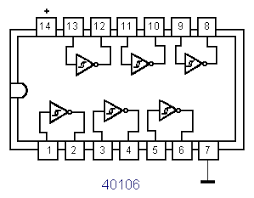
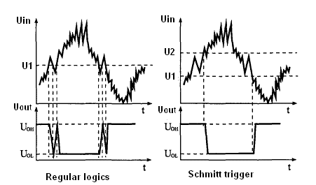
Another frequently used IC for inverters is the 40106, which contains six Schmitt triggers. A Schmitt trigger is an inverter with hysteresis. But what exactly is hysteresis?

It refers to a property where the output of a system depends not only on its current state but also on its past state. By setting different thresholds for “stepping up” and “stepping down,” the system avoids wavering in ambiguous middle zones. This allows the system to remain stable and unfazed by external fluctuations or minor noise. In short, it is a more stable, noise-filtered inverter, and it is preferred in oscillator design due to that very reliability. (See the diagram below)

Hysteresis Diagram 1 Hysteresis Diagram 2

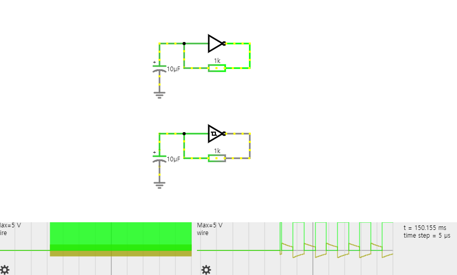
The interesting part of choosing between these two lies right here. Usually, one would choose the Schmitt trigger for its robustness against noise, as the 4049 seems to require a lot of effort to produce a clean square wave. To investigate further, I decided to compare the two side-by-side. This kind of comparison is an experiment that can only be done out of “ignorance”—a lack of prior knowledge. I designed the oscillators as follows:

Oscillator Comparison Design

Theoretically, in the design above, both should oscillate properly. The formula for calculating frequency is $1 / (RC \times t)$. I also learned that the value of $t$ (propagation delay) can usually be found in the datasheet. Looking at the waveforms at the bottom of the diagram, you can see that the frequencies of the two inverters are completely different. Specifically, the 4049 oscillator practically runs wild because it allows even the most minute changes to pass through. It’s a noise hellgate!

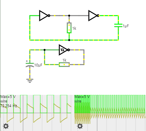
Consequently, I realized that to build an oscillator with the 4049, one must mix multiple oscillators together. In other words, you have to pass through various inverter gates to self-correct. The design is as follows:

4049 Mixed Oscillator Design

Through this experiment, my choice naturally gravitated toward the more “problematic” one. Starting with the 4049 and my first oscillator design, I built three oscillators into a single IC and began tinkering. I tried connecting different points, breaking connections, and replacing capacitors with different values or materials. The first circuit I created is shown below:

First Tinkered Circuit

At this point, a question arose: where should I listen to the sound? When working with analog, the starting and ending points are often unclear. For someone like me, who values tinkering over the “orthodox” way, the sheer number of choices was a bit paralyzing. So, I initially used the output junction shown above. When connecting to other equipment (e.g., a mixer), both devices must share the same ground, and the audio cable should not interfere with the signal flow. A good way to prevent this is to build a simple pre-amp using an Op-amp. I’ll explain the Op-amp some other time—that story is quite long!

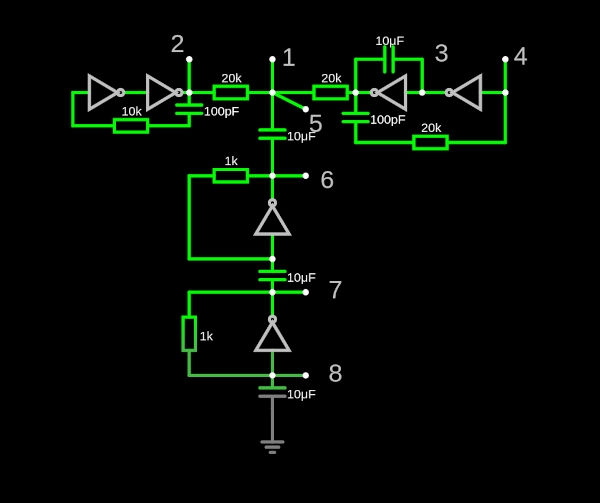
So, the final design came out like this:

Final Circuit Design

Each point is numbered; these are the contact points where I can interfere with the circuit in various ways. This idea was actually inspired by the Crackle Box. I created multiple contact points in advance so that the character of the circuit changes depending on how each point meets. Unexpectedly, it works quite well.

The following is a video of the test. This attempt eventually became the catalyst for composing my 2024 work, Cross-wired Xylophone.

‘Buoyants’ in Grotekerk, Veere

헤이그에서 오랫동안 알고 지낸 친한 친구인 Ludmila RodriguesMike Rijnierse가 지난 6월 초 아주 반가운 전화를 해왔다. Zeeland, 내가 그때까지 한 번도 가보지 못했던 곳에 있는 아주 오래되고 흥미로운 교회에서 site-specific installation을 할 예정인데, 사운드를 맡아 달라는 것이었다. “아이고, 감사합니다!” 하고는 며칠 후 그들의 스튜디오에서 첫 미팅을 가졌다.

Veere라는 기차도 들어가지 않는 작은 마을에 자리한 Grotekerk(“큰 교회”라는 뜻으로, 네덜란드 도시마다 있는 대표 교회쯤으로 생각하면 된다)에서의 전시였다. Lud가 보여준 프린트물과 웹사이트 속 교회는 구조가 확 트여 있고 전시 공간으로도 운영되는 곳이었다. 실제로 박물관처럼 쓰이며 크고 작은 전시들이 열리고, 매년 Kerkmeester라는 프로젝트를 통해 예술가들이 커미션을 받아 전시를 하는데, 올해는 Lud와 Mike 차례였다. 그들이 말해 준 전시의 컨셉은 Underwater!

최근 예술계에는 환경과 인간 외 존재들에 관한 주제가 많다. 당대의 중요한 문제이기도 하고, 인간 중심의 사고에서 벗어나려는 흐름이기도 하다. 학생들도 종종 이런 주제를 다루니 낯설지는 않다. 그러나 내 흥미와는 거리가 있었던 이유는, 물속 환경을 이야기하려면 녹음을 해야 한다는 점 때문이었다. 나는 20년 가까이 전자음악에 몸담으며 단 한 번도 field recording을 해본 적이 없었다.

나는 왜 녹음에 흥미가 없었을까? 흥미로운 소리를 듣고 감동하거나 명상에 잠긴 적은 많지만, 그것을 작품으로 담는 방식은 내 작업 방향성과 달랐다. 다른 예술가들이 만든 field recording 기반의 작품을 듣는 것으로 충분하다고 생각해 왔다.

그런데 이번 프로젝트는 달랐다. “이제 안 해본 것을 해봐야 한다”는 강한 내적 목소리가 있었다. 이런 기회가 아니고서야 내가 뜨거운 햇볕이나 비바람 속에서 몇 시간을 마이크 들고 서 있을 리가 있겠는가.

실제로 최근 나는 다양한 변화를 시도했다. 2024–2025년에는 학교에서 Analog Studio 수업을 청강하며 완전히 새로운 방식으로 작품을 써 보기 시작했다. 물론 DIY 세계는 계속 확장 중이지만, 늦기 전에 새로운 것들을 경험해 보고 싶었다. 한 번으로 충분하다면 그걸로 족하지만, 그 과정이 내게 어떤 변화를 가져올지 모른다. 그래서 흔쾌히 “YES!”를 외치며 프로젝트에 돌입했다.

Grotekerk Veere
Some notes after the visit

7월 초, 한국에 휴가 가기 전 나는 Lud와 Mike와 함께 Veere를 방문해 내 인생 첫 field recording을 했다. 교회 공간을 둘러보니 동기부여가 폭발했다. 가장 흥미로웠던 것은 천장이 아주 높다는 점이었다. 우리는 2층에도 스피커를 두었고, 10미터 높이에 8채널(4개의 스테레오 페어), 17미터에는 4개의 스피커를 천장을 향해 배치했다. 옥토포닉이라기보다는 확산(diffusion)에 가까운 구성이었다.

내 상상 속에서 청자들은 물속에 있고, 17미터 위의 스피커는 마치 지상을 상징하는 듯했다.

집에 돌아와서는 수도꼭지, 샤워 등으로 샘플을 만들었고, Open Data Archive에서 과학 목적으로 업로드된 underwater recording들을 다운받았다. 그런데 들으면서 깨달은 것은 우리가 상상하는 “물속 소리”는 사실 미디어가 주입한 이미지라는 점이었다. 실제 소리들은 전혀 다르게 들렸다. 자갈을 긁는 듯하거나 crackle noise generator 같은 노이즈와 어쿠스틱 사운드가 섞여 있었고, 가끔 마이크를 툭툭 치는 듯한 소리가 들어 있어 ‘아, 레코딩이구나’ 하고 느끼게 했다.

그래서 오히려 나는 억지로라도 ‘물’의 이미지를 덧입혀야겠다고 생각했다. 물속 소리와 물 밖의 소리가 함께 모였다.

또 다른 재료는 Analog Studio에서 녹음한 신호들이었다. 단순히 물속 소리를 재현하는 것만으로는 예술적 의미가 없다고 생각했다. 나는 오히려 듣는 이의 상상력을 열어주고 싶었다. 그래서 synthetic sound들을 더해, 미지의 세계를 미지로 남기고자 했다.

결국 5–10분짜리 작품을 15개나 만들었고, 여름 내내 한국에서 시원한 물소리를 들으며 헤드폰으로 작업했다.


12채널 spatialization은 WFSCollider로 마무리했다. 레이어마다 다른 출력과 믹싱을 적용했고, 일부는 WFSCollider 패턴을 이용해 spatial motion과 sound modification이 일체화되도록 했다. 예컨대 granular한 처리를 하면서 density가 커지면 위치 이동의 편차(deviation)도 커지는 식이었다.

Field Recording

한국에서 돌아온 바로 다음날, 짐을 풀자마자 다시 Veere로 향했다. 시차 적응은 힘들었지만 주로 저녁에만 고생했고, 낮 동안은 mastering을 마무리했다. 걱정했던 17미터의 시간차도, 두 레이어가 뚜렷할 때와 모호할 때가 적절히 섞여 흥미로운 효과를 냈다. 그리고 후반에 추가된 bass shaker 덕분에, 귀를 바닥에 대면 천장에서 들려오는 소리가 바닥으로 전이되는 듯한 오묘한 효과도 느낄 수 있었다. 볼륨이 낮아도 청중이 온몸으로 소리를 느낄 수 있었다.

@Benjamin van der Spek Mike, Rob, Lud and I from the top left.
@Benjamin van der Spek

설치는 Lud, Mike이 함께 준비했다. 그 둘은 거대한 녹색 천에 핀과 줄을 설치하고 Rob이 만든 모터 인터랙션으로 파도를 만들어내는 장치(위의 이미지)였다. 단순해 보이지만 안정적인 대규모 움직임을 구현하기 위해 엄청난 노력이 필요했다. 셋다 정말 대단하다. (크레인 타고 17미터까지 올라가는 그런 작업은 나는 절대 못한다!)

음악은 약 두 시간 지속된다. 전시는 10월 26일까지 이어지고, 내년 봄 재오픈 예정이다. 많이 들 가서 보시길!

👉 grotekerkveere.nl